VIC-20 Part 4 - Inside the cartridge

Using the cartridge with several kilobytes of ROM (8kB, 16 kB ROM, or even more) is essential for VIC-20 games distribution since it increases significantly the space for graphics, music, and code from the original 3.5kB available on the unexpanded VIC-20. Not to mention that the game loading time is zero since it is available in the memory immediately after the cartridge is plugged in and VIC-20 is powered up.
That's why producing own cartridge is one of the goals I have set at the beginning (see VIC-20 Part 1 - Meet the 8bit beast) for the VIC-20 game development and now, for the first time, I had the opportunity to learn a little about them.
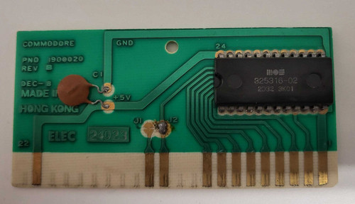
When I finally get an old cartridge I wanted immediately to examine it, so I eagerly opened the plastic box to see how it looks inside despite I know what to expect from the information on the Internet. But I just cannot help myself and I had to see it with my own eyes. Some cartridges have, what is called chip-on-board (COB), with die is glued to the PCB, and wires being bonded from it to pads all covered by epoxy resin, so it looks like a black blob (see here or here). Luckily mine did not have it - as shown on the image in the plastic box is nothing complicated - a simple PCB with the 8kB parallel OTP EPROM.
Besides the EPROM there is only one more component - a decoupling (smoothing) capacitor, which is soldered between VCC and GND. I expect its goal is to try to keep the voltage more constant. When the VIC-20 is powered up the capacitor is charged and then it waits until there is a voltage drop between VCC and GND. At this point, the capacitor will discharge to try to bring the voltage back to the level of charge inside the capacitor.
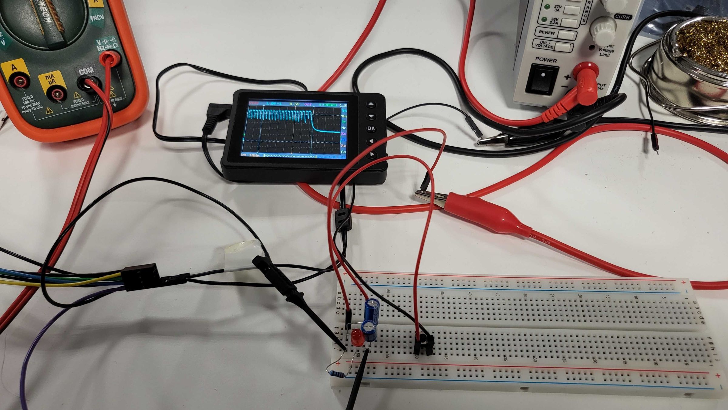
Since I'm an even worse electrician than the assembler programmer, I cannot resist practicing how the decoupling capacitor works. I have set up a simple test environment (well it took me 2 hours): I plugged into breadboard the red LED with voltage drop resistor, a few parallel capacitors, and a button. Repeatedly pressing and releasing the button simulated a voltage drop.

Test setup
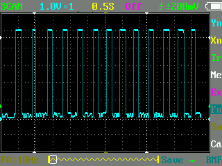
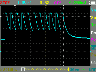
As you can see on the oscilloscope screenshots, the signal is smoother when capacitors are used, which is nicely visible when compared to a screenshot that shows the waveform of the circuit without capacitors.

Waveform for the circuit without capacitors

Waveform for the circuit without capacitors
Note: As you can see at the bottom of the second screenshot the capacitors are never entirely discharged because the red LED does not allow the current flow if the voltage drops below ~1.3 V, so the charge remains in a capacitor.
Happy New Year 2022 to everyone, whatever computer you use, programming, or love!
Escape From Rexal (VIC-20)
An attempt to create a game on the VIC-20 without any knowledge
| Status | In development |
| Author | 8bitsten |
| Genre | Platformer |
| Tags | VIC-20 |
More posts
- VIC-20 Part 5 - Moving a text: How to wait?Jan 01, 2022
- VIC-20 Part 3 - Drawing the horizontal lineDec 18, 2021
- VIC-20 Part 2 - Finally somethingDec 12, 2021
- VIC-20 Part 1 - Meet the 8bit beastDec 11, 2021
Leave a comment
Log in with itch.io to leave a comment.